The wenner and schlumberger test methods are both recommended with testing and interpretation.
Earth mat design ppt.
Use of e mix a conductive earthing compound with earth mats will always improve the earth resistance.
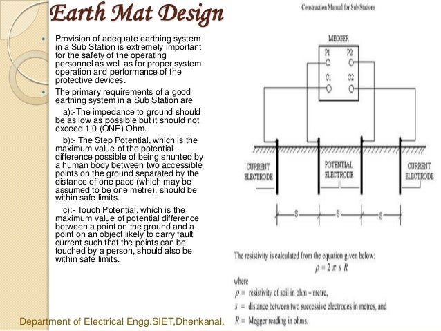
The grounding system in substation is very important.
It is well that the earthing systems are intended to protect equipment and personnel in and around the substation from the dangerous over voltage.
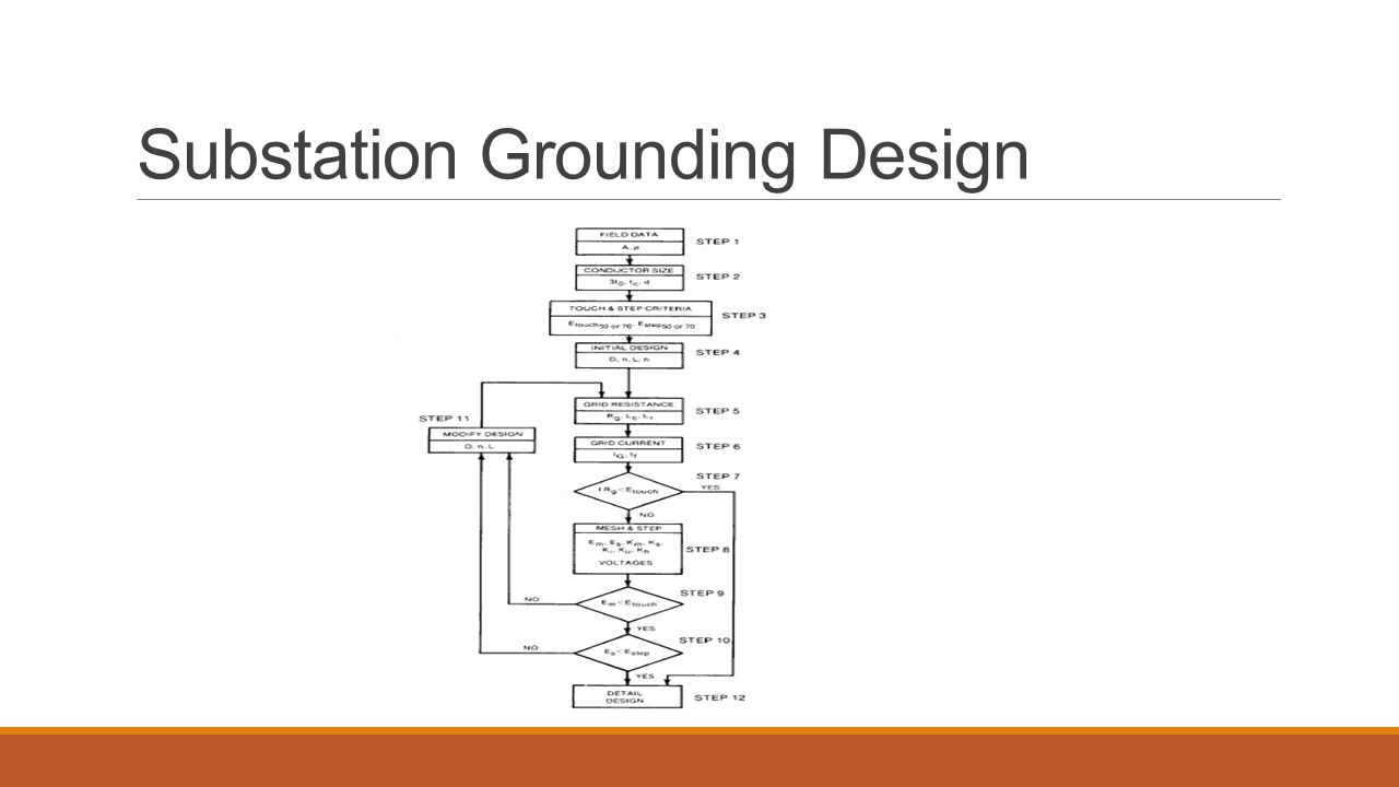
Design procedure of earth mat increase in horizontal conductor length actually reduces touch potential.
Earth mat design for 132kv substation in rivers state using etap pdf.
Earthing mat design for hv ehv substations.
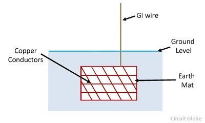
Earthing mat is made by joining the number of rods through copper conductors.
Earthing mat is mostly used in a placed where the large fault current is to be experienced.
Can t do the earth mat design separately for each step and finally connect each steps together.
So we have to effectively use conductor and down rod to minimize the step and touch potential within mat zone and beyond of.
Such type of system helps in limiting the ground potential.
It reduced the overall grounding resistance.
Earth mat design for 132kv substation in rivers state using etap pdf.
In this design these additional rods or mats are made to bond with the existing main ground mat and thereby assist in achieving the desired results.
Increase in no of down rod reduces step potential.
Auxiliary rectangular wire mats.
In high and medium voltage air insulated substations ais the electromagnetic field which causes are the static charges of bare cable and conductors and by the atmospheric conditions surges induce voltages at no live parts of the installation that create potential differences between metallic parts and ground and also between different points of.
Read about design of substation earthing system here.
Could u please explain me how to do the earth mat design for 220 132 33 kv outdoor gss which have 5 steps 135m 138m 141m 144m 147m.
Chemical electrolytic ground electrodes provide a low grounding resistance in areas of high soil resistivity and low.
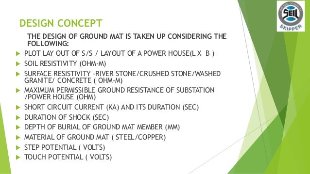
While designing an earth mat the following step is taken.
Standard crowfoot earth 25mm x 3mm copper tape x 5m long joined to a 70mm2 bcew tail 2m long.
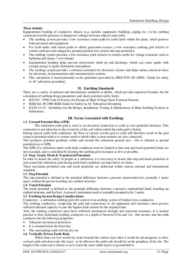
Introduction earthing is essential wherever electricity is generated transmitted and distributed or user to ensure safety and proper operation of the electrical system.
Increase in no of mesh in mat reduces the touch potential but beyond certain limit the mat is said to be saturated.
As earthing systems are installed near the surface of the earth the top soil layers being subject to higher current densities are the most significant and require the most accurate modelling.
Introduction to substation earthing grid.