Electrical Interlock System For Die Safety Blocks
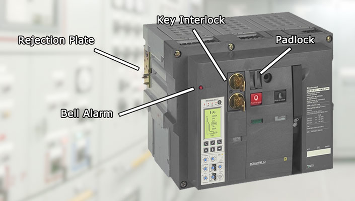
Circuit Breaker Safety Interlock Systems Explained
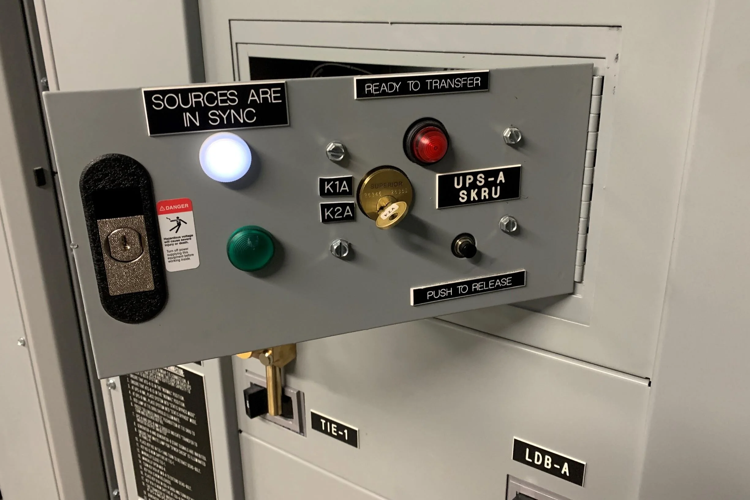
Safety Interlocks For Complex Electrical Power Systems Helios Electric

Failsafe Interlock Design Electronic Engineering Electronics Circuit Interlock

Safety Circuit Examples Of Safety Components Technical Guide Australia Omron Ia

The Function Of The Racking Mechanism Interlock Is To Prevent The Breaker From Moving From The Connection Position Before The Breaker I Breakers Circuit System

Circuit Breaker Bell Alarm With Lockout Explained Circuit Breakers Electrical Engineering

Die safety block calculations three factors need to be determined to guide the selection of safety blocks.
Electrical interlock system for die safety blocks.

Rockford Systems Page 7

Safety Gate Systems Pilz Au

Trapped Key Interlocking

Electrical Interlock Motor Control Forward Reverse Forward Reverse Circuit Diagram Youtube
Source : pinterest.com
